Filter and FilterSet
The filter model changed with the April 2010 release of the OME Schema. This page provides a description of the new structures used. The new structures are designed to work for Fluorescence Microscopy but are flexible enough it can also work with filter configurations for most other forms of microscopy.
Supported Objects
The schema supports the following objects:
- Dichroic
The dichroic mirror or dichromatic beamsplitter. This is used for the primary dichroic of the instrument. Other dichroics in the excitation or emission path can be modeled with the Filter object.
- Filter
This object is used to represent any type of excitation filter and emission/barrier filter. It contains details of the transmittance of the filter. It can also be used to model a dichroic mirror or dichromatic beamsplitter in the excitation or emission path.
- FilterSet
A FilterSet belongs to an Instrument in an OME-XML file and has alongside it any Filters and Dichroics it refers to. It is designed to represent a collection of filters available on a certain instrument. It can also represent a filter cube or filter block. To represent the set of filters used to collect an image, LightPath is a better choice. FilterSet may contain zero or more excitation Filters, one Dichroic, and zero or more emission Filters. No ordering of Filters is implied. Filters and Dichroics can be reused across multiple FilterSets. It will be normal to have a single Dichroic that is usable with several Filter combinations.
- FilterSetRef
These are used to attach a specific FilterSet from an Instrument to a Channel within an Image. They allow the FilterSet to be defined once in the instrument in an OME-XML file, and then used multiple times within the images.
- ManufacturerSpec
The Manufacturer spec is used by both Dichroic and Filter to store the Manufacturer, Model, SerialNumber and LotNumber of the optical element.
- FilterWheel
This is a value within a Filter used to record which holder the filter is located in. Although it is named after a wheel, it could just as easily be a filter slider or other mechanism. These holders allow any of their containing Filters to be automatically selected by the microscope control software.
- LightPath
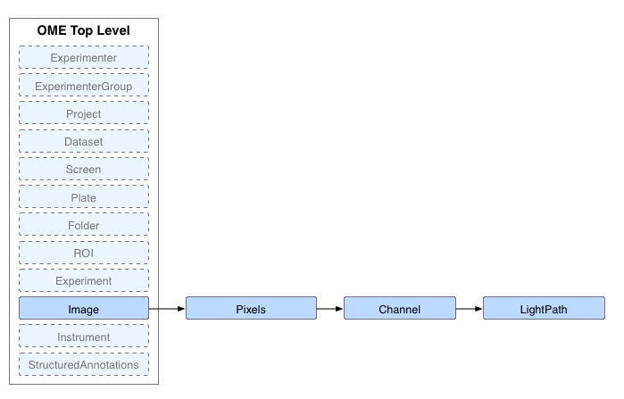
The LightPath object is a child of Channel and is used to represent the collection of Dichroic and Filters used to create the Channel. FilterSet is on an Instrument granularity, LightPath on a Channel of an Image.
Filters and Dichroics in the optical path

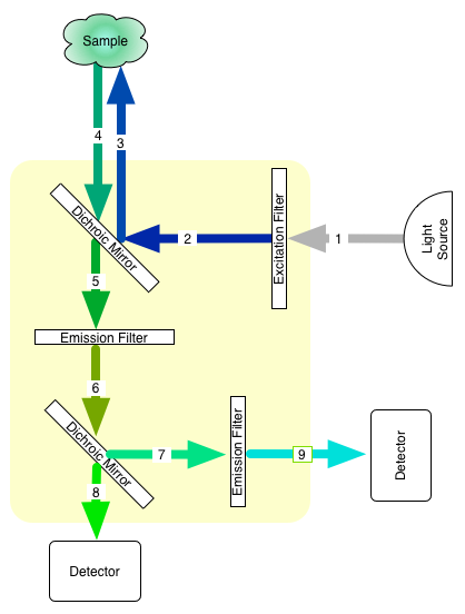
Sample instrument light path
Key for figure Sample instrument light path
The source produces a beam of light.
A small range of wavelengths are passed through the filters in the excitation path.
The light is selectively reflected by the dichroic mirror to illuminate the sample.
The fluorphore in the sample absorbs the light from 3 and re-emits it on a new wavelength. Some of this re-emitted light travels towards the dichroic mirror.
The light on the new wavelength is selectively transmitted by the dichroic mirror.
The wavelength of detected light is further narrowed and stray reflections reduced by the filters in the emission path.
The light can be optionally split by a dichroic in the emission path to go to two, or more, detectors. This dichroic is modelled as a Filter of type “Dichroic”.
The split light beam can travel directly from the dichroic to a detector.
The beam may be further filtered before reaching a detector.
Filter data structure in OME-XML
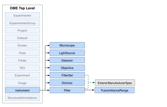
The Filter data elements are part of the central OME Schema. The filters are part of the Instrument block. Each instrument can contain zero or more filters, dichroics, and filter sets. Each filter set uses unique IDs to refer to the filters and dichroic it contains. If there are any additional filters used with the Channels within an image, then those filters are also defined at the instrument level, and referenced from the channel with a LightPath element using the unique ID. The Filters and Dichroics are both extensions of the ManufacturerSpec element so store this common data. A filter also contains one TransmittanceRange element that describes its optical characteristics.

Where FilterSet sits in the OME Schema
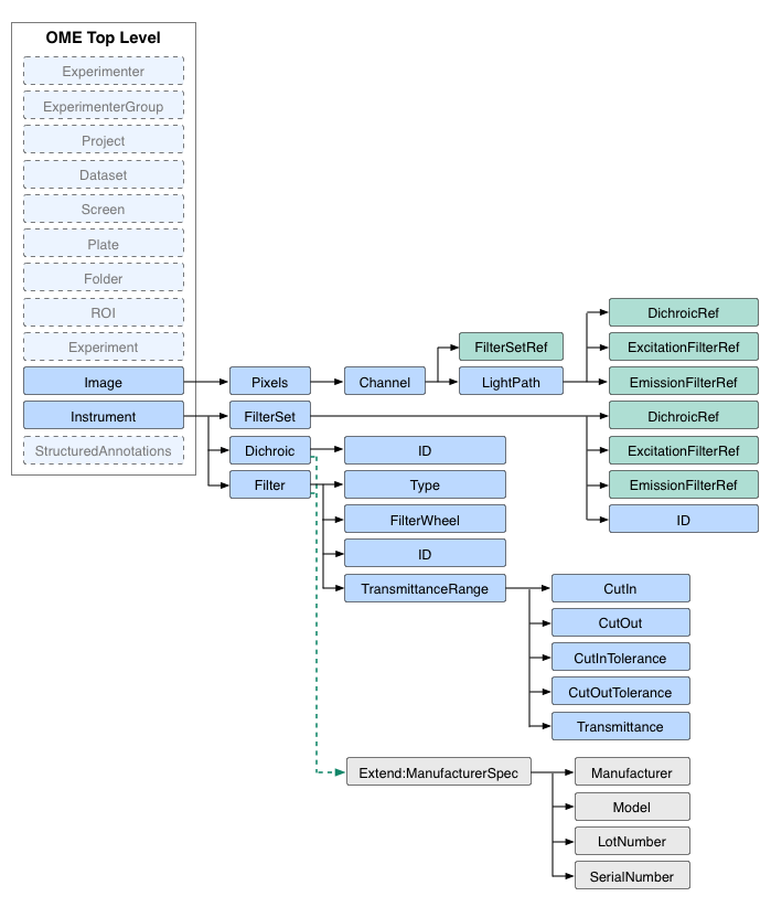
The FilterSet contains three kinds of references, one to a dichroic ID called DichroicRef, and two sets to filter IDs called ExcitationFilterRef and EmissionFilterRef. Each of the three kinds are optional. There is no distinction between a filter designed for emission or excitation at the Filter level. The distinction is made within the FilterSet (or LightPath) by the assignment of the filter ID reference to either a ExcitationFilterRef or EmissionFilterRef. Not all the objects in a FilterSet need to be used at the same time, and there is no ordering implied within the groups of references.
The Dichroic object simply contains its unique ID and the values it gets from extending ManufacturerSpec. In ManufacturerSpec, each object can have a SerialNumber and/or a LotNumber. The LotNumber is more commonly used in Filters and Dichroics so the batch of manufacture is recorded.
The Filter object has the values it gets by extending ManufacturerSpec and a unique ID the same as the Dichroic. It also has a Type and a FilterWheel value. In addition to these extra values, it contains one TransmittanceRange object. The TransmittanceRange describes the optical characteristic of the filter and has values for the CutIn and CutOut, along with the CutInTolerance and CutOutTolerance, all expressed in nanometers. There is also the Transmittance of the filter expressed as a percentage fraction.

Where LightPath sits in the OME Schema
The LightPath contains three kinds of references, one to a dichroic ID called DichroicRef, and two sets to filter IDs called ExcitationFilterRef and EmissionFilterRef. Each of the three kinds are optional. There is no distinction between a filter designed for emission or excitation at the filter level. The distinction is made within the LightPath by the assignment of the filter ID reference to either an ExcitationFilterRef or EmissionFilterRef. The key difference between LightPath and FilterSet is that ALL the filters in a LightPath have been used and their order is specified.

Attributes within the Filter objects
Sample pieces of .ome.xml files
Note
The sample sections below are taken from filter.ome.xml
This first example shows the Instrument side - the Filter/Dichroic/FilterSet structure of the resulting xml.
It defines six Filters; five are standard filters, the sixth is a dichroic used as a filter.
It defines two Dichroics that can represent the primary Dichroic in an instrument.
FilterSet:1 contains Filter:1 and/or Filter:2 for excitation, Dichroic:1 and Filter:3 and/or Filter:4 for emission.
<FilterSet ID="FilterSet:1" Manufacturer="Ink Inc." Model="Mk 3"
    LotNumber="K753">
    <ExcitationFilterRef ID="Filter:1"/>
    <ExcitationFilterRef ID="Filter:2"/>
    <ExcitationFilterRef ID="Filter:3"/>
    <ExcitationFilterRef ID="Filter:4"/>
    <DichroicRef ID="Dichroic:1"/>
    <EmissionFilterRef ID="Filter:5"/>
    <EmissionFilterRef ID="Filter:6"/>
</FilterSet>
<FilterSet ID="FilterSet:2" Manufacturer="Ink Inc." Model="Mk 3"
    LotNumber="K753"/>
<Filter ID="Filter:1" Manufacturer="Ink Inc." Model="Medium 490"
    LotNumber="J23" Type="BandPass" FilterWheel="Disk 7">
    <TransmittanceRange Transmittance="0.80" CutIn="450" CutOut="530"/>
</Filter>
<Filter ID="Filter:2" Manufacturer="Ink Inc." Model="Medium 520"
    LotNumber="J34" Type="BandPass" FilterWheel="Disk 7">
    <TransmittanceRange Transmittance="0.75" CutIn="500" CutOut="570"/>
</Filter>
<Filter ID="Filter:3" Manufacturer="Ink Inc." Model="Medium 580"
    LotNumber="J12" Type="BandPass" FilterWheel="Disk 7">
    <TransmittanceRange Transmittance="0.85" CutIn="550" CutOut="620"/>
</Filter>
<Filter ID="Filter:4" Manufacturer="Ink Inc." Model="Medium 630"
    LotNumber="J09" Type="BandPass" FilterWheel="Disk 7">
    <TransmittanceRange Transmittance="0.90" CutIn="590" CutOut="680"/>
</Filter>
<Filter ID="Filter:5" Manufacturer="Ink Inc." Model="Output 724"
    LotNumber="J34" Type="MultiPass">
    <TransmittanceRange Transmittance="0.75" CutIn="500" CutOut="570"/>
</Filter>
<Filter ID="Filter:6" Manufacturer="Ink Inc." Model="Medium 762"
    LotNumber="J12" Type="MultiPass">
    <TransmittanceRange Transmittance="0.85" CutIn="550" CutOut="620"/>
</Filter>
<Filter ID="Filter:7" Manufacturer="Ink Inc." Model="Medium 672"
    LotNumber="J09" Type="ShortPass">
    <TransmittanceRange Transmittance="0.90" CutIn="590" CutOut="680"/>
</Filter>
<Filter ID="Filter:Dichroic:2" Model="MirrorBlock Mk II" LotNumber="M538"
    Type="Dichroic"/>
<Dichroic ID="Dichroic:1" Model="HFT 405/488/543/633"/>
<Dichroic ID="Dichroic:3" Model="MirrorBlock MK II" LotNumber="M539"/>
This second example shows the Image side - the LightPath structure of the resulting xml.
Channel:1 defines a LightPath that uses Filter:1 for excitation, Dichroic:1, then Filter:2 and Filter:6 for Emission in that order.
Channel:2 defines a LightPath that uses Filter:1 for excitation, Dichroic:1, then Filter:2, Filter:6 and Filter:5 for Emission in that order.
Channel:3 references FilterSet:1, from this we do not know which of the filters in that FilterSet were used and in which order.
Dichroic:2 though defined above is not used by this Image.
<Image ID="Image:0" Name="405100percentsetting">
    <OME:AcquisitionDate>2008-06-19T00:39:00</OME:AcquisitionDate>
    <Description>Sample Image</Description>
    <InstrumentRef ID="Instrument:0"/>
    <ObjectiveSettings ID="Objective:0:0"/>
    <OME:Pixels ID="Pixels:1" DimensionOrder="XYCTZ" Type="int16"
        SizeX="128" SizeY="128" SizeZ="1" SizeC="2" SizeT="1">
        <Channel ID="Channel:1">
            <LightPath>
                <!--  ordered collection  -->
                <ExcitationFilterRef ID="Filter:1"/>
                <ExcitationFilterRef ID="Filter:Dichroic:2"/>
                <DichroicRef ID="Dichroic:1"/>
                <EmissionFilterRef ID="Filter:5"/>
            </LightPath>
        </Channel>
        <Channel ID="Channel:2">
            <FilterSetRef ID="FilterSet:2"/>
            <LightPath>
                <EmissionFilterRef ID="Filter:6"/>
            </LightPath>
        </Channel>
        <MetadataOnly/>
    </OME:Pixels>
</Image>