ROI model
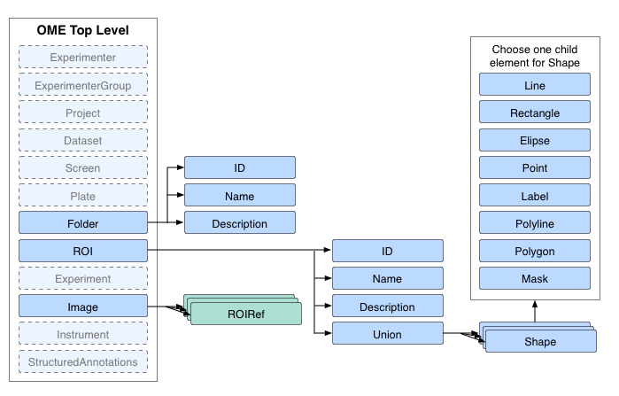
ROIs are a top level object within the OME node of the model. This means that they can be referred to from more than one point within the model:
- They can be referenced by an Image node.
- They can be referenced by a MicrobeamManipulation node.
- They can be standalone - we interpret this as meaning they are a template that could be applied by the user to images.
Note
A fourth case is possible but not recommended. It is possible for one ROI to be referenced by both an Image node and a MicrobeamManipulation node. The problem with this is the ROI for the MicrobeamManipulation should be fixed, but the ROI on an Image is something that should be editable by a user. In this case, the user can inadvertently change the ROI set during the MicrobeamManipulation without realizing it.

ROI Model Overview
ROI attributes and simple children
The ROI node has some basic properties attached to it:
- An ID used to reference it from the Image and MicrobeamManipulation nodes.
- A short name for the ROI used in the user interface (optional).
- A longer description for the ROI used in the user interface (optional).
- An annotation reference linking an annotation to this ROI (optional).
ROI complex children
The ROI node has a choice of ONE child operation node. At the moment, the only choice is Union, meaning it is composed of the union of all its child shapes. It is implemented as a choice so we have the option available of adding other composition methods in the future. There are currently no plans in place for this however.
Shape types
The shape types define the geometry and appearance of the ROI. Each shape is a 2D object that exists within a single Z plane of an Image. (This will change with a future version of the schema).
Shape attributes and simple children
The shape abstract type has four groups of information which are attributes or simple children.
- General
- A short name for the Shape used in the user interface (optional).
- Links to Planes
- TheZ - the z-section this Shape is on (optional, if not specified then all the z-sections).
- TheT - the timepoint this Shape is at (optional, if not specified then all the timepoints).
- TheC - the channel this Shape is on (optional, if not specified then all the channels).
- Shape Display Options
- FillColor - the color of the fill - encoded as RGBA (optional).
- FillRule - which parts of the Shape to fill (optional).
- StrokeColor - the color of the stroke (optional).
- StrokeWidth - the width of the stroke in pixels (optional). This also has an optional length unit, StrokeWidthUnit.
- StrokeDashArray - e.g. “none”, “10 20 30 10” (optional).
- Text - a text label that can optionally be displayed on the Shape (optional).
- FontFamily - the font family used to draw the text (optional).
- FontSize - the size of the font in points (optional). This also has an optional length unit, FontSizeUnit.
- FontStyle - the style applied to the text (optional).
- Geometry Adjustment
- Transform - a transformation matrix represented by 6 values (optional).
Note
More information on transforms is available in this blog post.
Shape concrete implementations

Shape Implementations
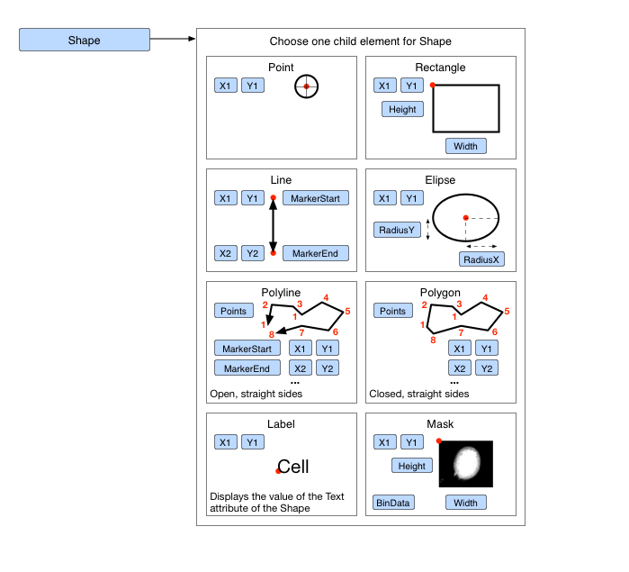
The Shape abstract type has eight geometry implementations. At the moment the choice is:
- Ellipse - specified by a centre point, a radius in the X-axis, and a radius in the Y-axis.
- Label - specified by a start point for the baseline for the first character.
- Line - specified by two end points, a markerStart (an arrowhead marker applied to the start of the line) and markerEnd (an arrowhead marker applied to the end of the line) (optional).
- Mask - specified by an upper left corner and a BinData block.
- Point - a simple x, y position.
- Polygon - specified by an array of coordinates that are connected by straight lines that are closed, a markerStart (an arrowhead marker applied to the start of the line) and markerEnd (an arrowhead marker applied to the end of the line) (optional).
- Polyline - specified by an array of coordinates that are connected by straight lines, a markerStart (an arrowhead marker applied to the start of the line) and markerEnd (an arrowhead marker applied to the end of the line) (optional).
- Rectangle - specified by an upper left corner and a width and height.
3D ROI
The current method of defining a ROI in three dimensions is as a Union of Shape objects, each of which defines the geometry where that 3D ROI would cut the 2D Plane the Shape is attached to.