Tiled images
Storing tiled images in an OME file.
Note
This approach is still valid but has been superseded by the 6D, 7D and 8D storage solution.
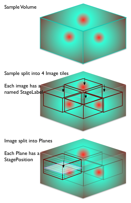
When you are looking at a sample that is larger than the available field of the microscope, one approach is to acquire a number of images, moving across the sample. These individual image pieces can then be joined together at a later date to form an image of the entire sample.
There are two structures in the model that support the joining process:
- StageLabel - part of Image
- Position - part of Plane
The mainstay of the OME format is the 5-dimensional pixel array. In order to maintain the integrity of this structure, the Tiling process has to be external to the Image structure. This means that you represent the Tiled image as a collection of Image elements. It is up to the software loading the OME file to interpret these individual Image elements as Tiles.
Each Image element can have a StageLabel. This is a named point in the co-ordinates of the microscope reference frame. The StageLabel has a Name attribute, that can store a human-readable description of the point, as well as X, Y, and Z values for the co-ordinates. Each co-ordinate is optional so an (X,Y) position or (X,Z) position can be recorded if required. This is probably best thought of as the target location for the individual tile.
During the acquisition process, the field is moved to capture each set of pixels making up a plane of an image of the tiled image. The exact location of the plane is recorded in the PositionX, PositionY, PositionZ on Plane. The Position values in Plane should correspond to the values in StageLabel but, depending on the instrument and capture method, there may be small discrepancies.
Note
Some systems in the past have used the Time value as a place to store the tile number of an image. This not the correct approach in the OME model.
Tile Samples Image
A sample file showing the structure is:
<?xml version="1.0" encoding="UTF-8"?>
<OME xmlns="http://www.openmicroscopy.org/Schemas/OME/2012-06"
    xmlns:xsi="http://www.w3.org/2001/XMLSchema-instance"
    xsi:schemaLocation="http://www.openmicroscopy.org/Schemas/OME/2012-06
                        http://www.openmicroscopy.org/Schemas/OME/2012-06/ome.xsd">
    <!-- This is a dummy file - it has no real data -->
    <!-- File to represent a tiled image aligned in a 2 by 2 grid -->
    <!-- as a collection of 4 images a, b, c, and d.  -->
    <!-- 0 | 1 | 2 | -->
    <!-- - | - | - | -->
    <!-- 1 | a | b | -->
    <!-- 2 | c | d | -->
    <!-- - | - | - | -->
    <!-- First image - this will be the tile at 1,1 on the grid -->
    <Image ID="Image:a" Name="2x2 Image">
        <AcquisitionDate>2008-03-01T18:13:51.0Z</AcquisitionDate>
        <StageLabel Name="(1,1) of 2x2" X="1.00" Y="1.00"/>
        <!-- X and Y (and Z if present) are the target location -->
        <Pixels ID="Pixels:a" DimensionOrder="XYZCT" Type="uint8"
            SizeX="128" SizeY="128" SizeZ="8" SizeC="1" SizeT="3">
            <BinData xmlns="http://www.openmicroscopy.org/Schemas/BinaryFile/2012-06"
                Length="10" BigEndian="true">
                <!-- ... -->
            </BinData>
            <Plane TheZ="1" TheT="1" TheC="1" DeltaT="0.01" ExposureTime="0.004"
                PositionX="1.03" PositionY="0.98" PositionZ="1.02" >
                <!-- X, Y and Z are the actual location when the plane was acquired-->
            </Plane>
            <Plane TheZ="2" TheT="1" TheC="1" DeltaT="0.02" ExposureTime="0.004"
                PositionX="1.03" PositionY="0.98" PositionZ="1.23">
            </Plane>
            <!-- ... and so on for the other Z sections -->
            <!-- ... and then for the other Time points -->
        </Pixels>
    </Image>

    <!-- Second image - this will be the tile at 1,2 on the grid -->
    <Image ID="Image:b" Name="2x2 Image">
        <AcquisitionDate>2008-03-01T18:13:51.0Z</AcquisitionDate>
        <StageLabel Name="(1,2) of 2x2" X="1.00" Y="2.00"/>
        <!-- X and Y (and Z if present) are the target location -->
        <Pixels ID="Pixels:b" DimensionOrder="XYZCT" Type="uint8"
            SizeX="128" SizeY="128" SizeZ="8" SizeC="1" SizeT="3">
            <BinData xmlns="http://www.openmicroscopy.org/Schemas/BinaryFile/2012-06"
                Length="10" BigEndian="true">
                <!-- ... -->
            </BinData>
            <Plane TheZ="1" TheT="1" TheC="1" DeltaT="0.31" ExposureTime="0.004"
                PositionX="1.02" PositionY="2.01" PositionZ="1.01">
                <!-- X, Y and Z are the actual location when the plane was acquired-->
            </Plane>
            <Plane TheZ="2" TheT="1" TheC="1" DeltaT="0.32" ExposureTime="0.004"
                PositionX="1.02" PositionY="2.01" PositionZ="1.24">
            </Plane>
            <!-- ... and so on for the other Z sections -->
            <!-- ... and then for the other Time points -->
        </Pixels>
    </Image>

    <!-- Third image - this will be the tile at 2,1 on the grid -->
    <!-- ... -->

    <!-- Fourth image - this will be the tile at 2,2 on the grid -->
    <!-- ... -->
</OME>
An alternative valid form would have TiffData blocks instead of the BinData blocks. This would be used in the header of an OME-TIFF file.
